As the saying goes, everyone has a plan until they get punched in the mouth. The same goes for taking a design and turning it into a physical object. You may not have the tools or material you need, you may realize that in reality, things don’t operate the way that you want, or the way you designed something just isn’t feasible to build. The other side of the coin is that maybe you come up with a better design while you build.
Building the DIY Repeat-O-Meter, most of the above happened. This doesn’t lead to a pretty finished product. Extra holes drilled throughout the part to try one one idea or another. Slots roughly cut, then a design change halfway through. It’s not the best work I’ve ever done. But I’ve built enough prototypes at this point, that I at least expect this sort of thing to happen.
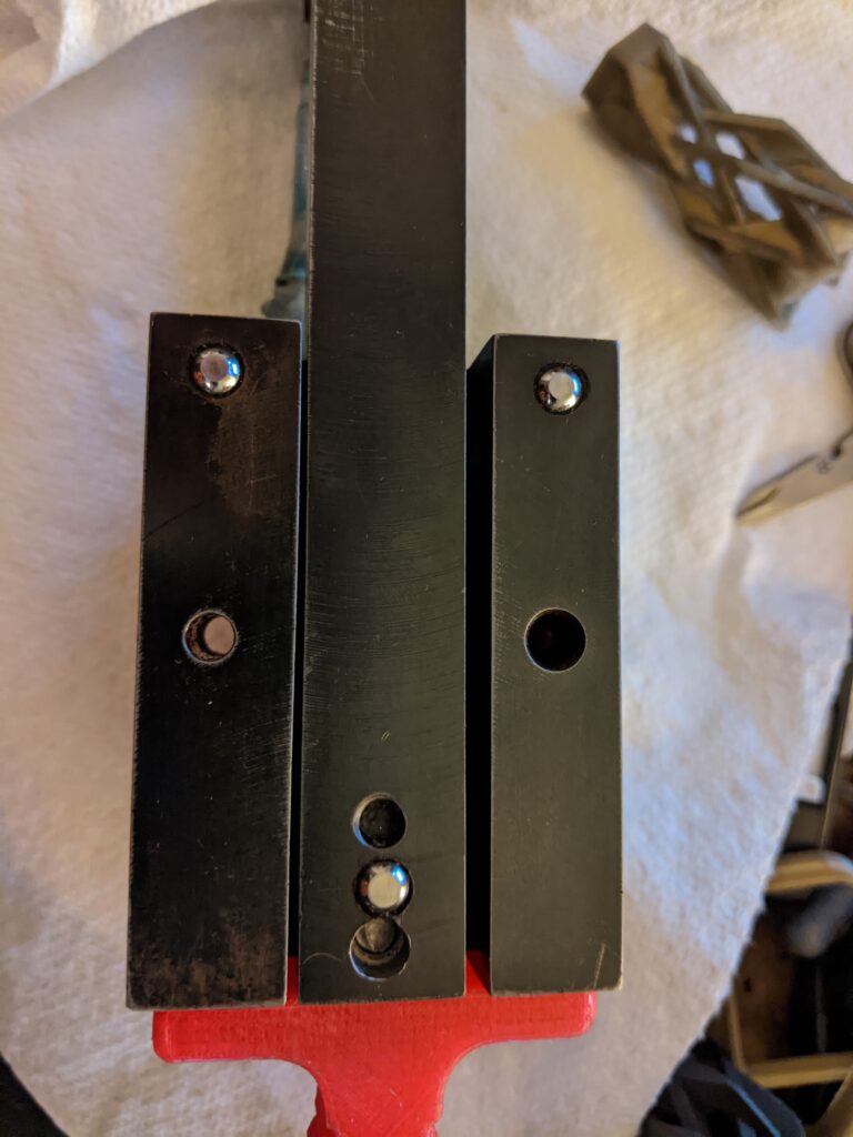
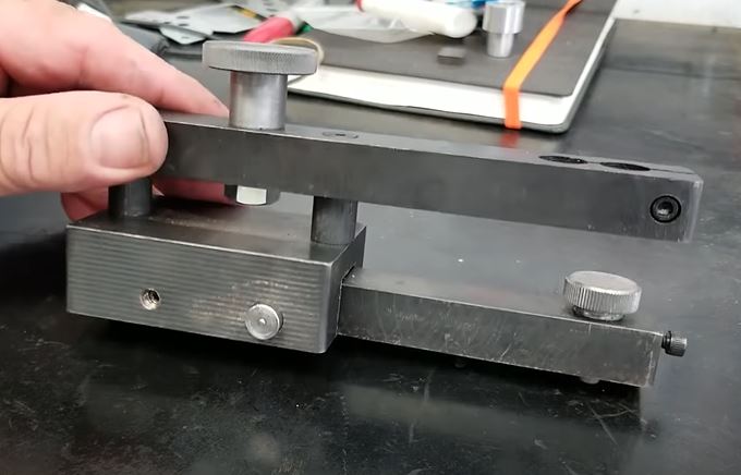
Excellent machining! Good job centering that slot. Nice Extra holes on the side of the base. The two holes on the back of the arm by the foot are where the arm connects to the base via two screws, and one was re-drilled for some reason? (I think I was going to originally try and put the ball for the foot in the very back?)
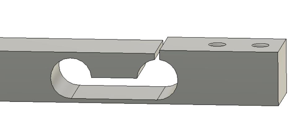
The most difficult part was determining how much of a slot, and how thin of a web to leave on the arm to get reliable flexing, that would not lead to permanent deformation, but be “soft” enough to provide good readings. It took a bit of experimentation, but I finally arrived at something that seemed like it would work.
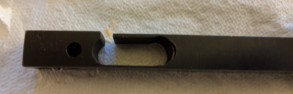
The Flexure. She ain’t pretty, but she works. It took a bit of trial and error to get the right amount of flex. And once again, an extra hole from the original design.
I like OpenSCAD for a number of reasons. It can be quick and easy to make simple, geometric objects very quickly. It’s my goto (pun intended) app for designing something quick when the dimensions are already known. It’s great for parametric designs, which allow for quick changes to a basic design. It’s one 3d modeling tool out of many, and I use it more than many others.
However, OpenSCAD does have it’s limits. To be fair, a large part of it’s limitations are on the user. If you know how to do the math in order to model an object, there’s a good bet OpenSCAD can do it. But as I’m not a mathematician, I’m limited in what I can create with it. (But if you want to see what real mathematician’s can do with OpenSCAD, check out MathGrrl (Lauren Taalman), Henry Segerman, and kitwallace (Chris Wallace))
That said, at the same time, OpenSCAD allows me to stumble upon accidents that I wasn’t actually trying to create. It’s one of the best features of OpenSCAD in my opinion. Accidental Modeling.
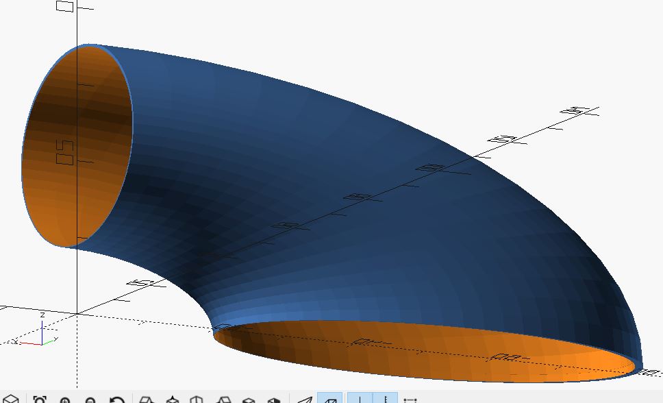
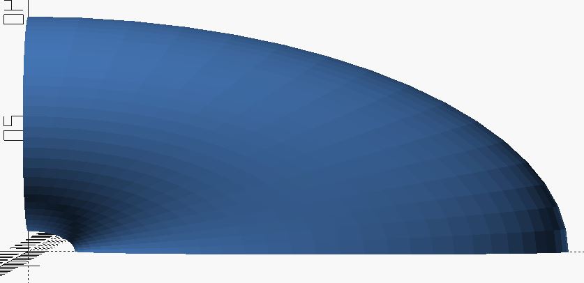
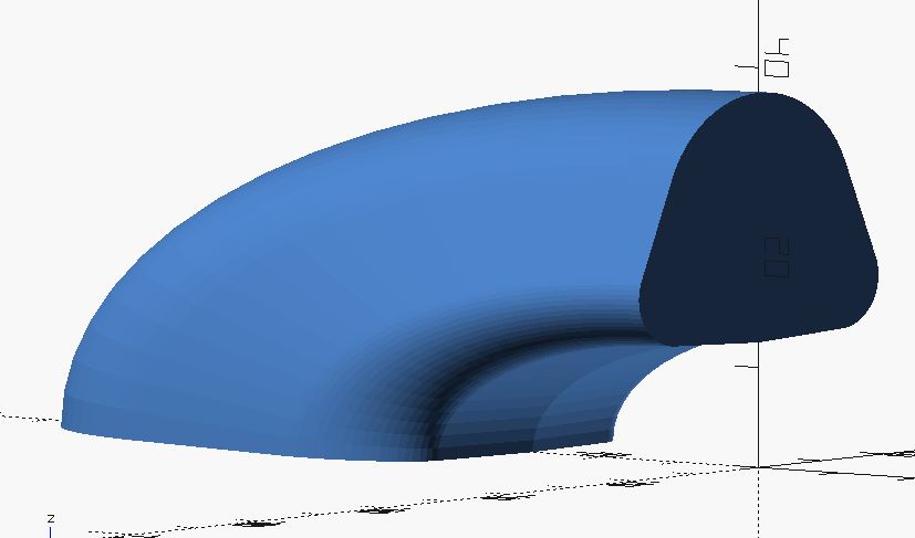
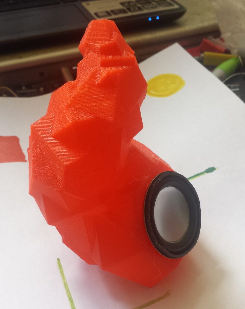
Sometimes I start modeling one thing, only to find myself accidentally creating something completely different. The air scoop was one of these happy accidents. I don’t even remember what I was trying to model, but I did a rotate_extrude, and there it was.
A second scoop, designed for the intake opening to be closer/lower to the output.
And then all that’s left is to make some parameter tweaks, and you can get different shapes. Now all I have to do is to make a dragster so that I can 3d print these and place it on the hood.
With some relatively minor changes, you can make a more complex shape.
The Code. Just remember, that like 99% of my programs, the parameters are designed for a sweet spot. Once you take it out of that range, it’s probably going to have problems. The good news is that this might help you make your own happy little accident.
//sgn - july 2017
//air scoop test - work in progress
//I recommend getting the shape, then just scaling it for correct size.

$fn = 64;

scale_x = 2.3;
scale_y = 1.2;
scale_z = 1;
main_diameter = 26; //has to be below 40. because it runs into itself if translation value stays at 22.
translation_value = 22;  //sort of height of scoop

//test one
//main body
difference(){
scale([scale_x,scale_y,scale_z])
rotate([90,270,0])
rotate_extrude(angle=90, convexity=10)
   translate([translation_value, 0])
    circle(d = main_diameter);

//subtractive copy
scale([0.98,0.98,0.98]){
translate([-0.5,0,0.3])  //these values will need to be played with sometimes to get the openings correct
scale([scale_x,scale_y,scale_z])
rotate([90,270,0])
rotate_extrude(angle=90, convexity=10)
   translate([translation_value, 0])
    circle(d = main_diameter);


//top opening
translate([-0.55,0,translation_value + 0.3])  //these values will need to be played with sometimes to get the openings correct
scale([scale_x,scale_y,scale_z])
rotate([0,90,0])
cylinder(d = main_diameter, h = 1.1);


//bottom opening
translate([-51.11,0,-0.1])  //these values will need to be played with sometimes to get the openings correct
scale([scale_x,scale_y,scale_z])
cylinder(d = main_diameter, h = 1.1);
}
}
Having bought a small, cheap, granite surface plate (12″ by 8″), that (I think) was Grade B (as compared to the AA and A which are better), it totally makes sense to check it’s relative flatness. Because the work I do in my bedroom requires high precision. Or at least that’s what I told myself.
a Rahn Repeat-O-Meter at a hefty 10″ long would barely have fit on my tiny surface plate. Forget about trying to take any type of systematic measurements with it. Instead of building a full size Repeat-O-meter, I’d have to create a smaller version in order to have it work on my small surface plate.
So let’s do this. Let’s spend hours of our life designing, developing, and building a small DIY repeat-o-meter, that I’m going to be unsure of it’s actually accuracy and repeatability. And let’s not mention the fact that you need a millionth’s (0.00005″) level indicator to actually do this, which are not cheap.
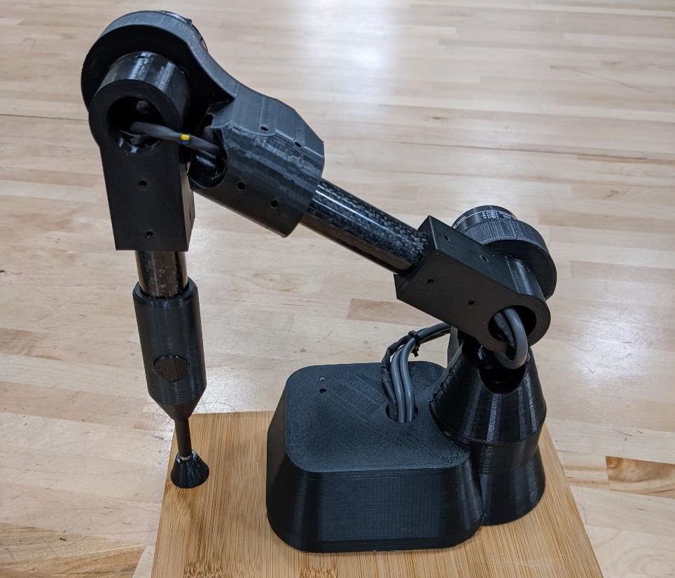
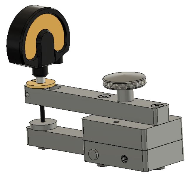
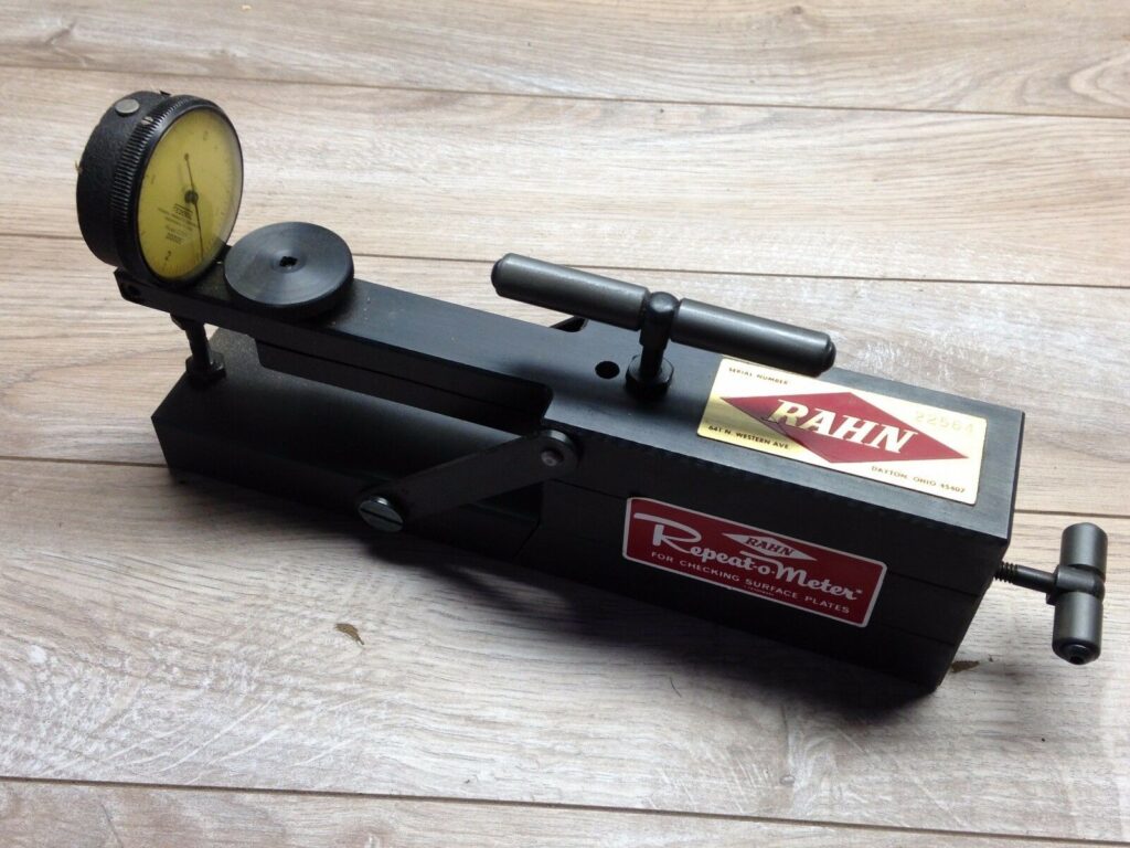
The First Design. The BarZ design. The Base is on the right. The Dial Indicator is the yellow faced instrument held in the cantilever arm. And the lever arm is at the bottom left, where it influences the dial indicator’s plunger, providing for the reading. The round part on the top is just a handle.
Taking the blueprints from the BarZ DIY Repeat-O-Meter, I started in Fusion360 and built a model almost exactly to the ShadonHKW prints. Immediately changes were made to the design. Partly because of available stock, partly because of available hardware (I was doing this on the cheap, I had to drop some money on a good indicator… which would cost more than the surface plate.) But also because I didn’t know what I was doing.
The basic design is simple, as referenced in an earlier post, you have a base with 3 flat feet that holds the dial indicator out on a cantilever post. This post sits above the lever arm. The lever has one foot at the front. As you move the device across the surface plate, the lever arm will influence the dial indicator, giving you a reading of the variations of the flatness of the surface plate.
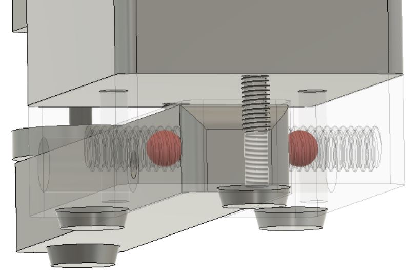
Looking from the back, and through the base, you can see the ball bearings here, held in by set screws. Note the triangular layout of the 3 feet on the bottom of the base, and one at the front on the lever arm.
For the Pivot, the BarZ design uses two center drilled holes on the lever, and two ball bearings (held in by set screws) on the base. While this should work just fine, I never built this version. The original Rahn Repeat-O-Meter uses a flexure hinge, and that design appealed to me, and as I’ve never made a flexure hinge before, I really wanted to try to see how a flexure hinge worked. At the time, I’m sure I was reading about compliant mechanisms. (And for more flexures and compliant mechanisms, check out this excellent Veritaseum video.)
One of the benefits of a flexure hinge is that I can worry less about the stiction/friction between the ball bearings and the lever arm itself. While this would normally not be an issue at all, when dealing with measuring millionths of an inch, and being moved across a plate, any little friction/stiction could possibly add error to my measurements.
The design for my first flexure. I don’t know what I’m doing. Designed to be easily machinable (two holes, a slot between them, and a saw cut.)
For the simple flexure hinge, I just designed a slot into the arm, taking material off the bottom where the actual flexing will occur until there would be a good “hinge” but it wasn’t so weak that I had to worry about permanent deformation or failure from metal fatigue. I read up a bit on the topic and found some numbers of around 0.050″ for my use case. That said, it wasn’t a scientific process at all. “Okay, that looks right” and “we’ll see how it works in metal” was the best I could come up with.
And with that, the design process was done. And all that was left was to make the thing. Of course it never seems to work that way.
While learning how to machine using the lathe and mill, I became interested in what seemed to me a chicken/egg problem; “How do you make a precision instrument if you don’t have a precision instrument to make it with?” The answer: it starts with a flat surface, and you build up from there. (For more about this answer, I recommend “Foundations of Mechanical Accuracy” by Wayne Moore.)
Precision starts with a flat plane. Without a smooth, regular surface, it would be nearly impossible to create square objects, and from there, impossible to build all the machines and technologies to create the world around us. (Also, I can’t help but mention that as I wrote this, I was reminded of the flat plane of Central Place Theory by Christaller, for the geography nerds out there.)
And thus my unhealthy obsession with flatness began.
I started with reading about Surface plates, the granite plates that have been ground to millionths of an inch flatness. A typical surface plate you may see in a shop would be 24″ by 36″ and 4″ thick, cut from granite and ground flat with diamonds. (For a very bad copy of the Federal Specification from the GSA, which almost all surface plate manufacturers base their tolerances on, because you can’t easily find the new spec, see here: the older spec, GGG-P-463c, now superseded by ASME B89.3.7.) In order to meet these standards, you need to have your surface plate calibrated, so how do we go about doing that?
And this is where I came across the weird looking thing, with the name straight from the 1950’s: the Rahn Repeat-O-Meter.
The Rahn Repeat-O-Meter. I don’t think you can use it to bust ghosts, but I’ve never tried.
A Repeat-O-Meter measures the variation in relative flatness across the surface plate. It’s a rather simple device, consisting of essentially a floating lever attached to a base. The base has an arm above the lever that holds a high precision dial indicator (0.00002″usually.) The lever lifts the plunger on the dial indicator as you sweep the whole thing across your surface plate. And as you move the Repeat-O-Meter around your plate, you see the variation in the flatness of your plate (relative, because it shows the variance from one point on the plate compared to another point.) Obviously, the less variance, the better the plate for high precision work.
When I googled the Repeat-O-Meter, I came across one of my favorite machinist Youtube Channels, Oxtoolco (Tom Lipton) and his videos on the Repeat-O-Meter and re-surfacing his granite plates, and his collaboration with NYCCNC on re-creating their own DIY Repeat-O-Meter. (And by the way, you’re going to see a lot of references to Tom Lipton on this blog when it comes to metrology, flatness, and all things machining. He’s my spirit animal.) And just as an aside, I’d be remiss not to mention this amazing design by Robin Renzetti.)
However, my biggest influence was the guys at Bar Z. This video (and their blueprints found in the description of the video) of their own DIY mini Repeat-O-Meter.
Now, I didn’t learn all this all at once. I had been reading and watching these videos over a period of a few months. And in that time, I had enough use for a surface plate that I bought a small (12″ x 8″) import granite surface plate from Ebay. And not knowing how flat this rather inexpensive and small plate was, I wanted a wear to investigate it’s properties. So I set out to make my own Repeat-O-Meter.
I designed this a few years ago just having fun with OpenSCAD. I had a small speaker that I needed a small enclosure for, and I wanted to test my new 3d printer at the time as well. So I came up with this design.
small 3d printed speaker enclosure
And the OpenSCAD Code:
//weird ass speaker cabinet for ~1.5 inch speaker. sgn June 2017
$fn = 6;
 translate([0,0,102]){
 rotate([195.57939, 29.244305, 54.377626]){  //puts it so base is flat, used repetier "lay flat" to find these numbers.
 difference(){