
The Repeat-O-Meter continues. The Design Phase
Having bought a small, cheap, granite surface plate (12″ by 8″), that (I think) was Grade B (as compared to the AA and A which are better), it totally makes sense to check it’s relative flatness. Because the work I do in my bedroom requires high precision. Or at least that’s what I told myself.
a Rahn Repeat-O-Meter at a hefty 10″ long would barely have fit on my tiny surface plate. Forget about trying to take any type of systematic measurements with it. Instead of building a full size Repeat-O-meter, I’d have to create a smaller version in order to have it work on my small surface plate.
So let’s do this. Let’s spend hours of our life designing, developing, and building a small DIY repeat-o-meter, that I’m going to be unsure of it’s actually accuracy and repeatability. And let’s not mention the fact that you need a millionth’s (0.00005″) level indicator to actually do this, which are not cheap.
Taking the blueprints from the BarZ DIY Repeat-O-Meter, I started in Fusion360 and built a model almost exactly to the ShadonHKW prints. Immediately changes were made to the design. Partly because of available stock, partly because of available hardware (I was doing this on the cheap, I had to drop some money on a good indicator… which would cost more than the surface plate.) But also because I didn’t know what I was doing.
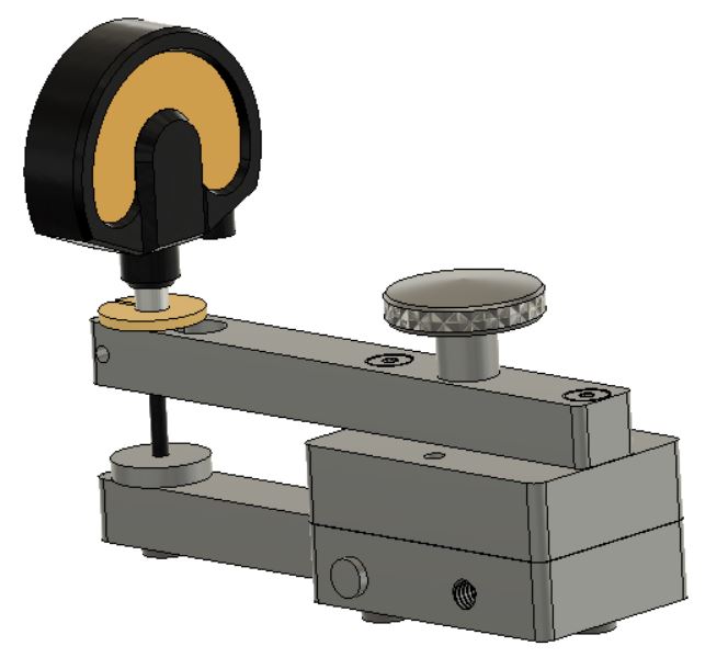
The basic design is simple, as referenced in an earlier post, you have a base with 3 flat feet that holds the dial indicator out on a cantilever post. This post sits above the lever arm. The lever has one foot at the front. As you move the device across the surface plate, the lever arm will influence the dial indicator, giving you a reading of the variations of the flatness of the surface plate.
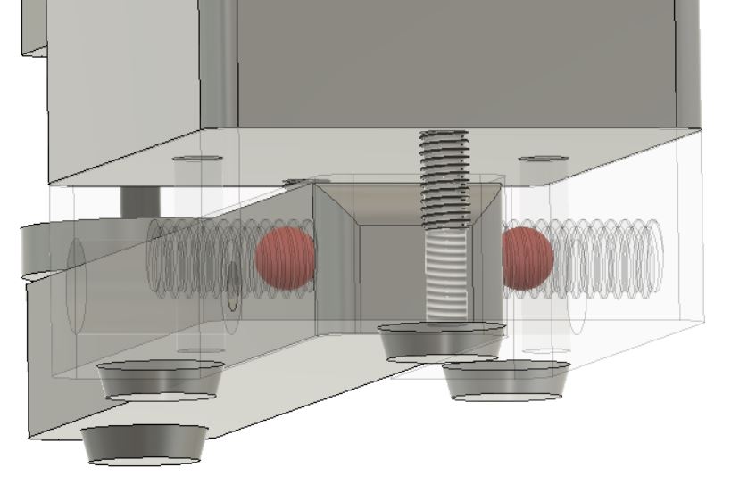
For the Pivot, the BarZ design uses two center drilled holes on the lever, and two ball bearings (held in by set screws) on the base. While this should work just fine, I never built this version. The original Rahn Repeat-O-Meter uses a flexure hinge, and that design appealed to me, and as I’ve never made a flexure hinge before, I really wanted to try to see how a flexure hinge worked. At the time, I’m sure I was reading about compliant mechanisms. (And for more flexures and compliant mechanisms, check out this excellent Veritaseum video.)
One of the benefits of a flexure hinge is that I can worry less about the stiction/friction between the ball bearings and the lever arm itself. While this would normally not be an issue at all, when dealing with measuring millionths of an inch, and being moved across a plate, any little friction/stiction could possibly add error to my measurements.
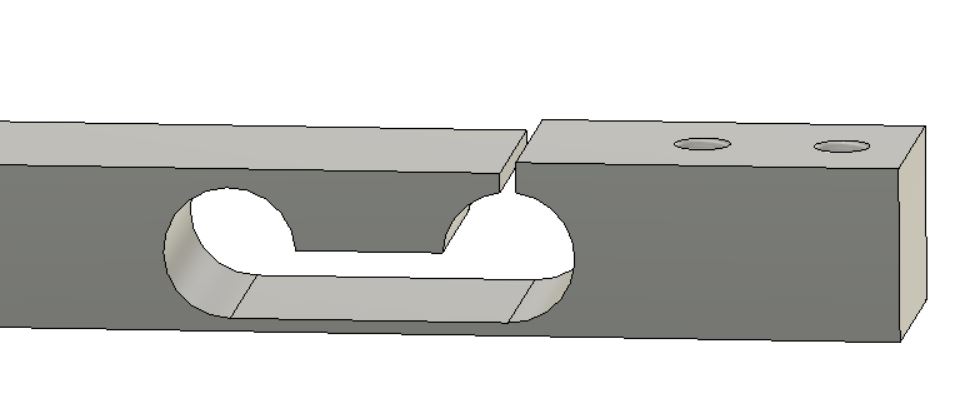
For the simple flexure hinge, I just designed a slot into the arm, taking material off the bottom where the actual flexing will occur until there would be a good “hinge” but it wasn’t so weak that I had to worry about permanent deformation or failure from metal fatigue. I read up a bit on the topic and found some numbers of around 0.050″ for my use case. That said, it wasn’t a scientific process at all. “Okay, that looks right” and “we’ll see how it works in metal” was the best I could come up with.
And with that, the design process was done. And all that was left was to make the thing. Of course it never seems to work that way.
(Next: “Wow, you call yourself a machinist?”)